


Please Leave Us A Message
Privacy statement: Your privacy is very important to Us. Our company promises not to disclose your personal information to any external company with out your explicit permission.

QRE
 July 08, 2021
The switching power supply transformer is a Power Transformer with a switching tube. In addition to the voltage conversion function of the ordinary transformer, the circuit also has the functions of insulation isolation and power transmission, which are generally used in switching power supplies and the like involving high frequency circuits. The switching power supply transformer and the switching tube together form a self-excited (or other) type of intermittent oscillator, thereby modulating the input DC voltage into a high frequency pulse voltage.
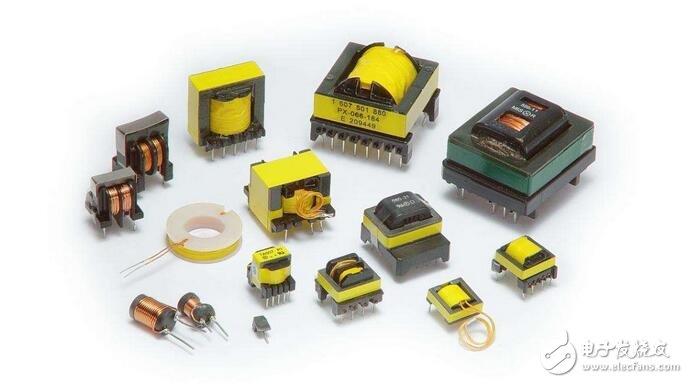
It plays the role of energy transfer and conversion. In the flyback circuit, when the switch is turned on, the transformer converts the electric energy into a magnetic field and can be stored, and is released when the switch is turned off. In a forward circuit, when the switch is turned on, the input voltage is directly supplied to the load and the energy is stored in the storage inductor. When the switch tube is turned off, the energy storage inductor performs a freewheeling flow to the load. Convert the input DC voltage to the various low voltages required.
How to reduce the loss of switching power supply transformers:Reduce copper loss
1. Use a lower current density;
2, reduce the number of turns, but will increase the magnetic flux density of the core and increase the iron loss, when the copper loss is significantly higher than the iron loss, use with caution;
3. Change the transformer process to reduce the winding AC resistance. The method has the main methods of reducing the diameter of the copper wire (not reducing the total cross-sectional area), increasing the primary and secondary adjacent faces (increasing the primary and secondary distributed capacitance), reducing the primary and secondary distances (increasing the primary and secondary distributed capacitance), coil sparseness, etc. ;
4, change the circuit operating parameters to reduce the AC resistance, such as reducing the switching frequency, but will increase the magnetic flux density of the core and increase the iron loss, when the copper loss is significantly higher than the iron loss, use with caution;
5. Use a lower resistivity wire.
Reduce iron loss
1. Use a magnetic core material with better power consumption parameters, such as PC50 material using TDK instead of PC40 material;
2, reduce the magnetic flux density, but will increase the number of turns of the coil and lead to increased copper loss, with caution;
3, change the circuit parameters, such as reducing the switching frequency, but will increase the magnetic flux density at the same time, with caution, if necessary, with the winding turns adjustment;
4. Reasonable thermal design, using the valley value in the temperature and loss curve of the core material.
Integrated approach
1. According to the respective heat dissipation conditions, the proportion of copper loss and iron loss is reasonably allocated;
2. Reasonably design the magnetic flux density and working frequency of the core to make the core work in the best FB combination state.
Eddy current loss analysis of switching power supply transformers:The eddy current loss of the switching power supply transformer accounts for a large proportion of the total loss of the switching power supply. How to reduce the eddy current loss of the switching power supply transformer is an important content of the switching power supply transformer or switching power supply design. The principle of eddy current loss in transformer production is relatively simple. Since the transformer core is a good magnetic conductive material, it also belongs to a kind of electric conductor; when the alternating magnetic field line passes through the electric conductor, the electric conductor is in the electric conductor. An induced electromotive force is generated. Under the action of the induced electromotive force, a loop current is generated in the electrical conductor to cause the conductor to heat up; this phenomenon occurs because the alternating magnetic field lines pass through the conductor and generate induced electromotive force and loop current in the conductor. It is called eddy current because the loop current it produces is not output as energy, but is lost in its own conductor.
The calculation of the eddy current loss of a single-excited switching power supply transformer and the calculation of the eddy current loss of a double-excited switching power supply transformer are different in method. However, the method used to calculate the eddy current loss of a single-excited switching power supply transformer can be used to calculate the eddy current loss of a double-excited switching power supply transformer with a slight change. For example, the bipolar input voltage of a double-excited switching power supply transformer is regarded as a unipolar input voltage with two different polarities, so that the calculation of the eddy current loss of the double-excited switching power supply transformer can be realized. Therefore, only the eddy current loss calculation of the single-excited switching power supply transformer is analyzed in detail below.
When a DC pulse voltage is applied to both ends of the primary coil of the transformer, an excitation current is passed through the primary coil of the transformer, and a magnetic field strength H and a magnetic flux density B are generated in the transformer core, which are determined by the following equation. :
B = ΔB*t/τ + B(0) (2-44)
H = ΔH*t/ΔH + H(0) (2-45)
In the above formula, ΔB and ΔH are the magnetic flux density increment and the magnetic field strength increment, respectively, τ is the DC pulse width, and B(0) and H(0) are the magnetic flux density B and the magnetic field strength H at t = 0, respectively.
In order to reduce the eddy current loss, the conventional transformer core is generally designed such that a plurality of thin iron pieces, referred to as iron chips, are overlapped with each other, and the iron chips are insulated from each other. Figure 2-18 shows an iron core in a transformer core or transformer core. We can think of these iron chips as consisting of a very large number of "coils" (shown in dashed lines in the figure) that are tightly joined together; when the alternating magnetic lines of force pass vertically through these "coils", in these "coils" Induced electromotive force and induced current are generated. Because of the resistance of these "coils", these "coils" lose electromagnetic energy.
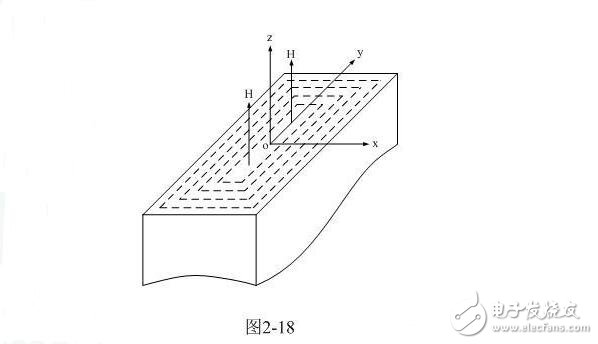
During the action of the DC pulse, the mechanism of the eddy current is substantially the same as the mechanism of the forward voltage output. The direction in which the eddy current generates the magnetic field is opposite to the direction in which the excitation current generates the magnetic field. The demagnetism is strongest at the center of the iron chip, and the demagnetism at the edge is zero. Therefore, the magnetic flux density distribution in the iron chip is not uniform, that is, the outermost magnetic field strength is the largest and the center is the smallest. If the eddy demagnetization is strong, the maximum value of the flux density may well exceed its average value, which is determined by the amplitude and width of the known pulse.
The magnetic field distribution along the cross section of the iron chip can be obtained using Maxwell's equation; Maxwell's differential equation is:
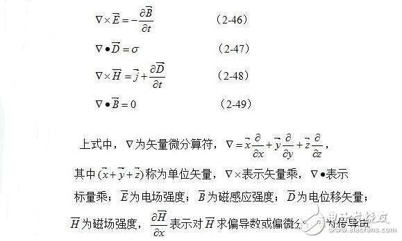
In the above formula, μa is the average magnetic permeability of the transformer core, ρc is the electrical resistivity of the iron core, and a negative sign indicates that the direction of the magnetic field generated by the eddy current is opposite to the direction of the magnetic field generated by the exciting current. Rot E and rot Hx represent the electric and magnetic field curls, that is, the vortex electric field and the intensity of the vortex magnetic field, respectively. Hx, Hy, and Hz are three components of the magnetic field strength H; Bx, By, and Bz respectively have three components of the magnetic induction intensity B; and Ex, Ey, and Ez have three components of the electric field strength H, respectively.
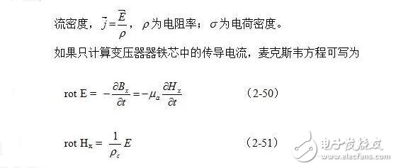
Since the hysteresis loop area of the single-excited switching power supply transformer core is small, its magnetization curve can basically be regarded as a straight line, and the magnetic permeability μ can also be regarded as a constant; therefore, the average magnetic permeability is used here instead of the meaning. Wide magnetic permeability.
As can be seen from Figure 2-18, the magnetic field strength consists of H = Hz: and Hx = Hy = 0; for electric field strength, the direction is parallel to the Y-axis is E = Ey, Ex = Ez = 0. Therefore, the above two formulas can be rewritten as:
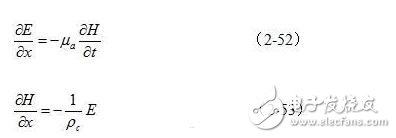
By classifying (2-53) and then substituting (2-52), the one-dimensional distribution equation of the magnetic field strength can be obtained as follows:
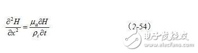
Since the voltage applied across the primary winding of the transformer is a DC pulse square wave, the growth of the magnetic field strength or flux density generated by the excitation current should be linear with time under steady state conditions, namely:
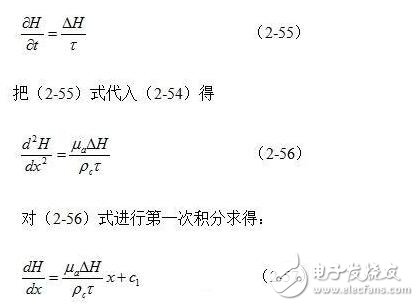
When x = 0, it is located at the center of the iron chip, where the magnetic field strength is the smallest, that is, the derivative value of this point is equal to 0, thereby obtaining the integral constant c1 = 0.
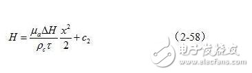
Perform another integration on (2-57):
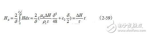
Since the average value Ha of the cross-section magnetic field strength in the transformer iron chip must be equal to the value required for electromagnetic induction at any time, that is, the requirement of the formula (2-45) is satisfied, so corresponding to FIG. 2-18 (2- 58) The average value is:
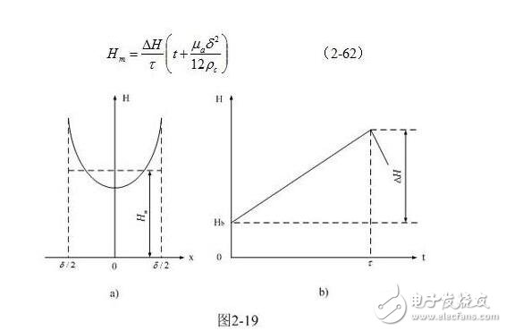
Substituting (2-60) into (2-58), the magnetic field strength in the iron chip under steady state conditions can be determined as:
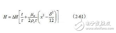
Fig. 2-19-a and Fig. 2-19-b are the functions H(x) and the time-distributed function H(t) of the magnetic field strength distribution in the iron chip given by (2-61), respectively. )Graph.
It can be seen from Fig. 2-19-a that due to the reversal magnetization of the eddy current, the magnetic field strength is the lowest in the center of the iron core or the iron core, and the edge magnetic field strength is the highest.
In Fig. 2-19-b, the linear growth with time is the magnetic field generated by the excitation current of the primary coil of the transformer; Hb is the magnetic field generated by the current supply of the transformer primary coil to compensate the demagnetization generated by the eddy current.
From Fig. 2-19-b, the influence of the eddy current loss on the magnetic field strength (average value) in the transformer core and the magnetic field generated by the current in the secondary coil on the transformer core magnetic field when the transformer is positively outputted, Basically the same. It is worth noting that the same result can be obtained by analyzing the y-axis direction in the same way.
It can be seen from Fig. 2-19-a that when x = δ/2, the maximum value of the magnetic field strength of the surface of the iron chip is:
The above is the Method for reducing switching power transformer loss and eddy current loss analysis of switching power supply transformer we have listed for you. You can submit the following form to obtain more industry information we provide for you.
You can visit our website or contact us, and we will provide the latest consultation and solutions
Send Inquiry
Most Popular
lastest New
Send Inquiry

Mr. James
Tel:
86-0571-82583721
Fax:
E-mail:
Related Products List
Mobile Site
Privacy statement: Your privacy is very important to Us. Our company promises not to disclose your personal information to any external company with out your explicit permission.
Fill in more information so that we can get in touch with you faster
Privacy statement: Your privacy is very important to Us. Our company promises not to disclose your personal information to any external company with out your explicit permission.